- 您现在的位置:买卖IC网 > Sheet目录261 > VVZB135-16NO1 (IXYS)RECT BRIDGE 3PH 135A 1600V E2
VVZB 135
150
A
90
A
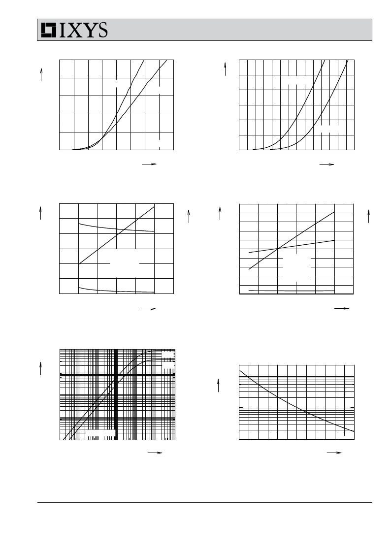
I C
120
T VJ = 25°C
T VJ = 125°C
I F
60
T VJ = 125°C
90
60
30
30
0
V GE = 15V
0
T VJ = 25°C
0.0
0.5
1.0
1.5
2.0
2.5
3.0
3.5 V 4.0
0.0
0.5
1.0
1.5
2.0
2.5
3.0 V 3.5
V CE
Fig. 9 Typ. output characteristics
V F
Fig. 10 Typ. forward characteristics of
free wheeling diode
E off
9
mJ
6
t d(off)
900
ns
600
t
E off
10
mJ
8
t d(off)
1000
ns
800
t
6
600
3
E off
V CE = 720 V
V GE = ±15 V
R G = 22 Ω
T VJ = 125°C
300
4
2
E off
V CE = 720 V
V GE = ±15 V
I C = 50 A
T VJ = 125°C
400
200
0
0
20
40
60
80
t f
0
100 A 120
0
0
10
20
30
40
t f
0
50 Ω 60
1
I C
Fig. 11 Typ. turn off energy and switching
times versus collector current
diode
R G
Fig. 12 Typ. turn off energy and switching
times versus gate resistor
K/W
0.1
Z thJC
0.01
IGBT
R
10000
Ω
1000
0.001
single pulse
0.0001
100
VVZB 135
0.00001 0.0001 0.001
0.01
0.1
1
s 10
0
25
50
75
100
125 °C 150
t
Fig. 13 Typ. transient thermal impedance
IXYS reserves the right to change limits, test conditions and dimensions.
? 2007 IXYS All rights reserved
T
Fig. 14 Typ. thermistor resistance versus
temperature
20070912a
5-5
发布紧急采购,3分钟左右您将得到回复。
相关PDF资料
VVZF70-16IO7
RECT BRIDGE 3PH 1600V FO-T-A
VW2X30-16IO1
MODULE AC CTLR 2X30A 1600V V1-A
VW2X45-16IO1
MODULE AC CTLR 2X45A 1600V V1-A
VWO140-16IO1
MODULE AC CTLR 3PH 1600V V2-PACK
VWO35-12HO7
MODULE AC CTLR 1200V ECO-PAC1
VWO60-16IO7
MODULE AC CTLR 3PH 1600V FO-T-A
VX-01-1C23
SWITCH BASIC SPDT .1A .187QC
VX-016-1A2
SWITCH SNAP 0.1A SPDT SOLDER
相关代理商/技术参数
VVZB170-16ioXT
功能描述:桥式整流器 Thyristor Module RoHS:否 制造商:Vishay 产品:Single Phase Bridge 峰值反向电压:1000 V 最大 RMS 反向电压: 正向连续电流:4.5 A 最大浪涌电流:450 A 正向电压下降:1 V 最大反向漏泄电流:10 uA 功率耗散: 最大工作温度:+ 150 C 长度:30.3 mm 宽度:4.1 mm 高度:20.3 mm 安装风格:Through Hole 封装 / 箱体:SIP-4 封装:Tube
VVZB170-16NO1
功能描述:桥式整流器 170 Amps 1600V RoHS:否 制造商:Vishay 产品:Single Phase Bridge 峰值反向电压:1000 V 最大 RMS 反向电压: 正向连续电流:4.5 A 最大浪涌电流:450 A 正向电压下降:1 V 最大反向漏泄电流:10 uA 功率耗散: 最大工作温度:+ 150 C 长度:30.3 mm 宽度:4.1 mm 高度:20.3 mm 安装风格:Through Hole 封装 / 箱体:SIP-4 封装:Tube
VVZF70
制造商:IXYS 制造商全称:IXYS Corporation 功能描述:Three Phase Rectifier Bridge
VVZF70-08io7
功能描述:SCR模块 70 Amps 800V RoHS:否 制造商:Vishay Semiconductors 开启状态 RMS 电流 (It RMS):260 A 不重复通态电流:4000 A 最大转折电流 IBO:4200 A 额定重复关闭状态电压 VDRM:1.6 kV 关闭状态漏泄电流(在 VDRM IDRM 下):20 mA 开启状态电压:1.43 V 保持电流(Ih 最大值): 栅触发电压 (Vgt): 栅触发电流 (Igt): 最大工作温度:+ 150 C 安装风格:Chassis 封装 / 箱体:INT-A-PAK
VVZF70-12io7
功能描述:SCR模块 70 Amps 1200V RoHS:否 制造商:Vishay Semiconductors 开启状态 RMS 电流 (It RMS):260 A 不重复通态电流:4000 A 最大转折电流 IBO:4200 A 额定重复关闭状态电压 VDRM:1.6 kV 关闭状态漏泄电流(在 VDRM IDRM 下):20 mA 开启状态电压:1.43 V 保持电流(Ih 最大值): 栅触发电压 (Vgt): 栅触发电流 (Igt): 最大工作温度:+ 150 C 安装风格:Chassis 封装 / 箱体:INT-A-PAK
VVZF70-14io7
功能描述:SCR模块 70 Amps 1400V RoHS:否 制造商:Vishay Semiconductors 开启状态 RMS 电流 (It RMS):260 A 不重复通态电流:4000 A 最大转折电流 IBO:4200 A 额定重复关闭状态电压 VDRM:1.6 kV 关闭状态漏泄电流(在 VDRM IDRM 下):20 mA 开启状态电压:1.43 V 保持电流(Ih 最大值): 栅触发电压 (Vgt): 栅触发电流 (Igt): 最大工作温度:+ 150 C 安装风格:Chassis 封装 / 箱体:INT-A-PAK
VVZF70-16io7
功能描述:SCR模块 70 Amps 1600V RoHS:否 制造商:Vishay Semiconductors 开启状态 RMS 电流 (It RMS):260 A 不重复通态电流:4000 A 最大转折电流 IBO:4200 A 额定重复关闭状态电压 VDRM:1.6 kV 关闭状态漏泄电流(在 VDRM IDRM 下):20 mA 开启状态电压:1.43 V 保持电流(Ih 最大值): 栅触发电压 (Vgt): 栅触发电流 (Igt): 最大工作温度:+ 150 C 安装风格:Chassis 封装 / 箱体:INT-A-PAK
VW-01
制造商:Thomas & Betts 功能描述:Universal Recessed Box And Cover
